Design elements
This part is suitable for optimizing the number of structural elements before the verification process. The members may be merged into design members and groups, it is also possible to rename the elements to simplify the identification in the project.
Design members and design groups
Any structural member is listed as an individual element in the part "Design" of the tree menu. All the necessary parameters for verification (buckling parameters etc) have to be specified for any of these members. This procedure may be long lasting for more complicated structures. To simplify the work, the members may be merged into design members and groups. The number of members for verification may be reduced significantly with the help of this procedure.
Design members (DM) may be used for merging the members of the same material (timber, steel, concrete) that lie in the same line. Merged members may have different cross-sections (except concrete structures). Only one member with the length equal to the total length of merged members will be transferred into the designing program when the design member is created. As the designing programs are using calculated diagrams of internal forces as an input, it is possible to merge members connected through inner hinges. The typical example of design member is the steel column with variable cross-section or the RC beam with more supports.
![]() Connected beams that may be merged into one design element
Connected beams that may be merged into one design element
Design groups (DG) is suitable for merging the members (members or design members) that have identical topology and may be verified as one member. The merged members have to have identical cross-section, length and orientation. The members in design group are transfferred into designing program as one member, however, number of verified cases is multiplied by the count of members in the group. The opposite orientation of members in group is permitted. The software shows a warning, as it may cause wrong results for members with unsymmetrical designing parameters (buckling properties etc.) along the member length.
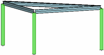
 Design group of columns (highlighted by green)
Input of design members and groups
The design members should be created before design groups, as design members may be merged into design groups. The design elements can be created manually (part "Selected" in the tree menu) or automatically (part "Generate"). For the manual work, the members for merging into design member or group has to be selected first (highlighted by green in the workspace). After that, corresponding tool ("Join to DM" or "Join to DG") can be used.
Automatic creation of design members and groups launches the dedicated window, that shows design elements which were recognized by the software. Table in the left part shows the list of proposed design elements, active one is highlighted also in the structure view. The table of design groups also shows the information regarding the direction of merged members (problem described above). The window contains the setting "Consider all generated elements", which provides an option to create only few of suggested elements. The choice of elements for creation can be done with the help of buttons in the first column of the table.
 Manual choice of design groups
Breaking design members and groups
Already created design elements may be broken back into the individual members. The active group or member (the active element is highlighted in the workspace and also by the bold font in the table of design elements) may be deleted with the help of the tool "Individually" - "Break". Similar way ("Selected" - "Break") can be used for selected elements. The tool "Break into members" in the tree menu deletes all design members and groups in the structure.
Renaming the dimensioning elements
Any design element may be described to simplify the identification in the structure. The name can be specified in the column "Description" of the table with design elements.
 User defined name of design element