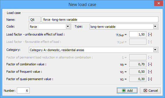
Load case
This window contains complete properties of the entered load case. Every load case is characterized by the name and by the ID code that is placed in front of the name. This ID code consists of the unique load case number and prefix. The prefix represents the type of load:
G |
|
Q |
|
A |
|
W |
|
S |
|
It means that first load case may have ID code G1 providing that the type of this load case is "permanent". ID code Q5 means that the load case represents the variable load and is placed on the fifth position in the list of load cases. ID code is used in the description of load combinations.
Code of load case
Code of load case determine the type of load that can be entered into the load case. These options are available:
Self-weight |
|
Force |
|
Deformation |
|
Temperature |
|
Load type
The load type represents the load character with regards to the variability in time. The range is based on the classification according to the chapter 4.1.1. of EN 1990. Variable loads are also divided in accordance with the table 2.1 of EN 1995-1-1 (design of timber structures).
Load factors
Partial load factors γf may be specified in this part. This factor takes account of the possibility of unfavourable deviations from the representative values of the load. Favourable (γf,inf) and unfavourable (γf,sub) effect of permanent loads shall be distinguished. Default values of factors are based on the table A1.2(B) of EN 1990.
Category
Range of available categories respects the sorting in the table A1.1 of EN 1990. This category is determinative for the selection of combination factors ψ0, ψ1 a ψ2 for variable loads. Category "User defined input" gives the option to specify arbitrary values of the combination factors.
Combination factors
The default values of these factors are based on the standard EN 1990 and depend on the category of the load case. Arbitrary values may be specified for the user defined input. Following factors are included:
ξ |
|
ψ0 |
|
ψ1 |
|
ψ2 |
|
Left bottom corner shows the ordinal number of the load case. The order of load cases in the list of load cases may by changed with the help of this value.
 Window "Load case"