Member properties
This window contains properties of member connected to the truss joint. The properties are organized into two tabs:
Member
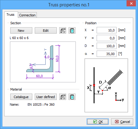
This part contains inputs of geometry and material. The member cross-section can be specified in the window "Cross-section editor", that can be launched by the button "New". The cross-sectional dimensions can be modified quickly with the help of the button "Edit". The button "![]() " is able to load cross-sectional properties from existing member. The button "
" is able to load cross-sectional properties from existing member. The button "![]() " shows the table with cross-sectional characteristics.
" shows the table with cross-sectional characteristics.
The material can be selected from pre-defined database (the button "Catalogue") or can be specified numerically with the help of yield and ultimate tensile strengths (the button "User defined"). These buttons aren't enabled, if the global material is assigned to all joints (in the default screen of the program). The button "![]() " is able to load material from existing member. The button "
" is able to load material from existing member. The button "![]() " shows the table with material characteristics.
" shows the table with material characteristics.
The member position is given by following dimensions:
X |
|
Y |
|
D |
|
α |
|
 Tab "Member"
Connection
The members can be connected in these ways:
- Bolted connection
- Welded connection
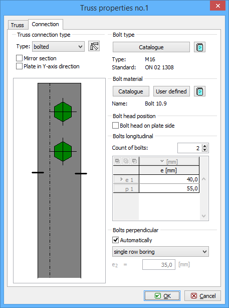
This choice can be done with the help of the setting "Type". The button "![]() " is able to load properties of connection from existing member. The setting "Mirror section" changes the position of protruding part of the cross-section. The conflict of two members can be solved with the help of the setting "Plate in Y-axis direction", that moves the member to opposite surface of the joint plate.
" is able to load properties of connection from existing member. The setting "Mirror section" changes the position of protruding part of the cross-section. The conflict of two members can be solved with the help of the setting "Plate in Y-axis direction", that moves the member to opposite surface of the joint plate.
The bolt properties have to be specified for bolted connection. The type and size of bolt has to be selected from pre-defined database, that can be opened with the help of the button "Catalogue". Bolt material can be selected from database (the button "Catalogue") or can be specified numerically with the help of yield and ultimate tensile strengths (the button "User defined"). These buttons aren't enabled, if the global material is assigned to all joints in the default screen of the program.
The rows count can be also specified. The distances between bolts can be calculated automatically or entered by the user.
Following dimensions are available for welded connections:
aw,p1 |
|
Lw,p1 |
|
aw,p2 |
|
Lw,p2 |
|
aw,v |
|
Lw,v |
|
 Tab "Connection"