Axial Symmetry
This computational model is suitable for the analysis of structures of revolution. This assumption must be satisfied from both the construction and load point of view. A typical example is the solution of vertically loaded isolated pile, excavation of circular ditch, or pumping of water from a circular hole.
 Axisymmetric analysis
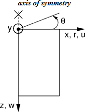
Similarly to the plane strain analysis the computational problem is three dimensional, which can, however, be transformed into a two-dimensional problem, see Figure. The analysis is then performed with respect to 1 m of arc length having diameter equal to x(r). The axis of symmetry always corresponds to the origin of the x(r) coordinate. Shear strain components in the direction of rotation can be neglected. We are then left with the stress and strain components acting on the plane of symmetry cut and the normal strain and stress component in the hoop (circumferential direction) direction. The corresponding non-zero components of the stress and strain vector are:
![]()
![]()
It is clear that the hoop strain, and therefore also the affected normal stresses, attains an infinite value at the axis of symmetry. Thus regarding the finite element approximation, arriving at reliable and sufficiently accurate estimates of these values requires a relatively fine mesh along the symmetry axis.
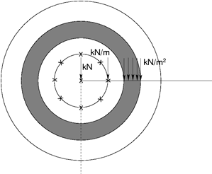
The application of line and surface load is also worth mentioning. Several examples of applying the load on terrain surface are displayed in the following Figure. Clearly, their effect increases with the distance from the axis of symmetry. Introducing such a type of load directly on the axis of symmetry has, therefore, no effect. In such a case it is necessary to choose the type of load of axis of symmetry. The program allows for the application of concentrated forces only.
 Examples of load applied on terrain surface
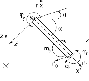
Considering beam elements the analysis corresponds to the solution of a plane membrane of revolution including bending effects. Non-zero degrees of freedom are identical adopted for beam elements in plane strain analysis. Apart from axial (meridian) effects it is necessary to consider also membrane and bending effects in the hoop direction, see the following Figure.
 Beam element in axial symmetry
The corresponding components of internal forces, see Figure, assumed with respect to 1 m of cross sectional width are given by:
![]()
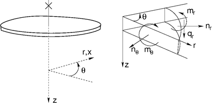
In a special case of a circular plate (angle α = 0) we may refer to radial and hoop components of internal forces, see the following Figure.
 Internal forces acting on a circular plate
Internal forces are related to corresponding strains and curvatures as follows:

After setting r equal to infinity we arrive at plane strain conditions. It is worth noting that in case of shear forces their magnitudes are, unlike the plane strain analysis, significantly dependent on the refinement of the finite element mesh. This holds also for vertical reactions.
Note to water flow
Recall that similarly to the reactions forces in the stress analysis the point fluxes at nodes with prescribed pore pressures are evaluated with respect to 1 m of arc length having diameter equal to x(r). In case of plane strain analysis the corresponding values are taken per 1 m run. The corresponding overall fluxes (inflow/outflow) can be determined from point fluxes [m3/day/m] as follows:
Plane strain analysis

Axisymmetric analysis

where N is the number of nodes along a given mesh line, in which the point fluxes Qi [m3/day/m] are calculated. In case of axisymmetric analysis xi represents the x-coordinate of a given point. Therefore, the axisymmetric analysis provides total the inflow/outflow [m3/day] through for example a cylindrical surface (vertical line) or circular surface (horizontal line).